

FD590 Composite Decking Profile

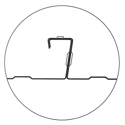
Formdeck FD590 decking is supplied in three base metal thicknesses of 0.75mm, 0.90mm and 1.0mm.
Experimental testing and analysis on the decking has been carried out in accordance with AS4600 – Cold Form Steel Structures and AS/NZS2327-2017 Composite structures – Composite steel-concrete construction in buildings to determine the characteristic properties of the profile for the design and use of the FD590 as composite decking.
FD590 Profile (per metre Width)
FD590 Design
The design of suspended slabs using the FD590 profile requires consideration of the profile decking under the following conditions:
Formwork Stage – during construction of the composite slab and considers placement of decking and associated reinforcement, concrete pouring and other loading associated with construction.
Design for the formwork stage is dependent on the applied loads and deflection limits in accordance as per AS/NZS 1170.1 and AS3610. Design may be carried out using engineering principles along with the characteristic properties outlined below or by using the FD590 Formwork Tables.
Composite Slab – after the concrete has reached it design strength and the profile acts with the concrete and other reinforcement to provide the required strength for loads arising throughout the life of the structure.
Design for the composite slab is carried out in accordance with AS/NZS2327-2017 based on the defined loading, the deflection requirements, the environmental conditions and any other design life considerations. The slab spanning capacities may be determined using the capacity tables for various slab thicknesses for varying degree of shear connection using the FD590 Composite Tables.
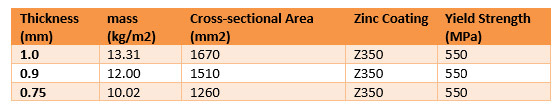
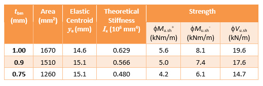
FD590 Design Properties
The characteristic Design properties used for both the formwork stage and composite design for the FD590 Profile are:
FD590 Profile Properties (per metre width)
Flexural Stiffness – Formwork Stage
The Flexural Stiffness for the sheeting has been derived from testing of the deck profile under both single and multiple span configurations with varying spans and thicknesses. The modulus of elasticity (E) of the steel sheeting is assumed to be 200,000MPa and yield strength (fy) of the sheeting is assumed to be 550MPa.
The stiffness of the profile is affected by the number of spans. The stiffness is defined by the following equations for single and multiple spans respectively.
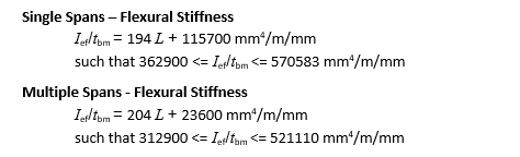
In both cases L is the free span of the of the decking and the thickness of the base metal (tbm) and measured in millimetres.
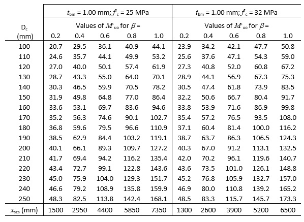
Composite Strength
The composite strength of the slabs of varying thickness are calculated in accordance with AS/NZS2327-2017 Composite structures – Composite steel-concrete construction in buildings -Section 2. The degree of shear connection (![]() ) is determined by the shortest distance from the point being considered to a free end of the deck. Full shear connection (
) is determined by the shortest distance from the point being considered to a free end of the deck. Full shear connection (![]() = 1) occurs when the profile decking has sufficient length (xscs) to fully engage the decking profile.
= 1) occurs when the profile decking has sufficient length (xscs) to fully engage the decking profile.
FD590 Composite Capacities M+uo – tbm = 1.00 mm (per metre width to AS/NZS 2327)
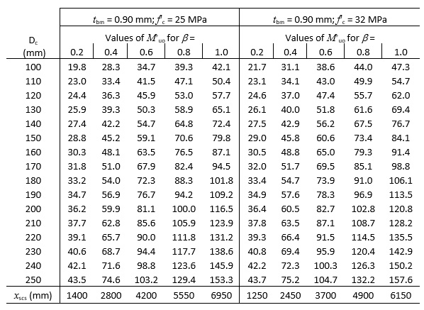
FD590 Composite Capacities M+uo – tbm = 0.90 mm (per metre width to AS/NZS 2327)
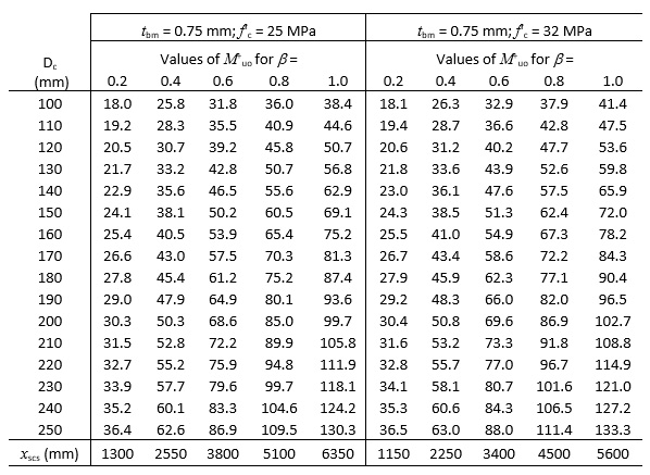
FD590 Composite Capacities M+uo – tbm = 0.75 mm (per metre width to AS/NZS 2327)
FD590 Formwork Tables
The formwork tables are generated utilising the flexural stiffness and strength as detailed under design properties.
The spanning tables have an allowance for concrete ponding and other loading in accordance with Australian Standards AS1170, AS3610 and AS2327 including the 4 kPa live load allowance for stacking materials.
Concentrated loading should be avoided at the sheet overlap joints and unsupported edges, and mounding of concrete above finished concrete levels should be avoided.
The following assumptions are made:
- Concrete density assumed to be 2400Kg/m3
- multiple spans are poured simultaneously to ensure deflection limits are maintained.
- Mounding of concrete during pour does not occur.
- support widths are 50 mm at profile ends and 100 mm over intermediate supports.
- multiple spans do not vary by more than 5% and that maximum spans are not exceeded.
Supporting structure and propping should be designed and verified as suitable for all loads cases by a registered engineer.
The theoretical deflections are based on the above assumptions and may vary depending on the density of the concrete, the weight of reinforcement or the sequence of the concrete pour.
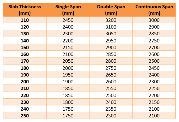
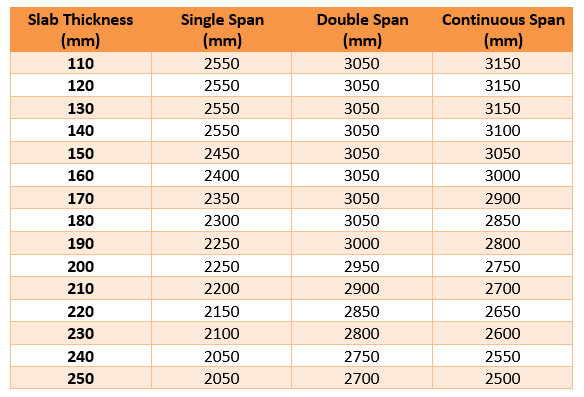
FD590 1.0 mm Base Metal Thickness
1.0 mm Base Metal Thickness – Deflection Limitation L/150
1.0 mm Base Metal Thickness – Deflection Limitation L/240
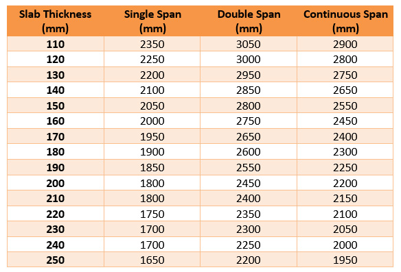
FD590 0.9 mm Base Metal Thickness
0.9 mm Base Metal Thickness – Deflection Limitation L/150
0.9 mm Base Metal Thickness – Deflection Limitation L/240
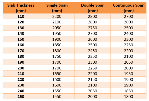
FD590 0.75 mm Base Metal Thickness
0.75 mm Base Metal Thickness – Deflection Limitation L/150

0.75 mm Base Metal Thickness – Deflection Limitation L/240
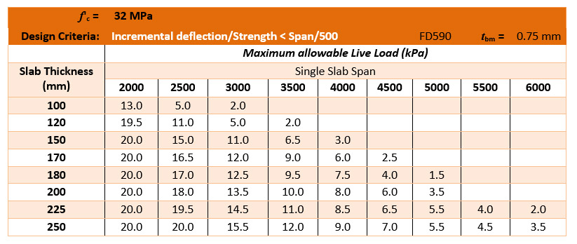
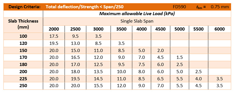
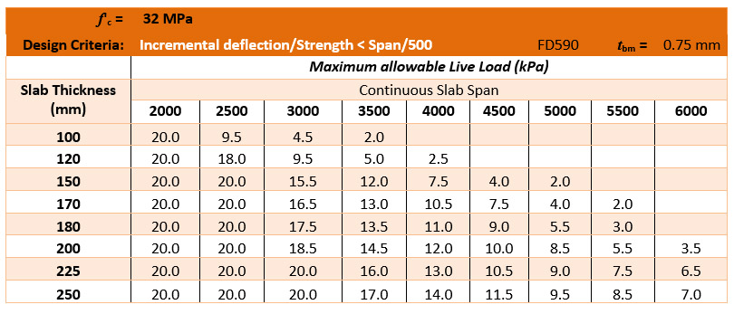
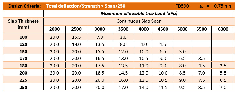
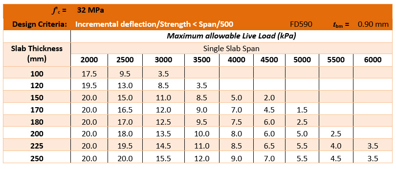
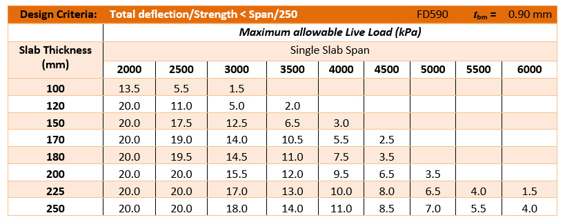
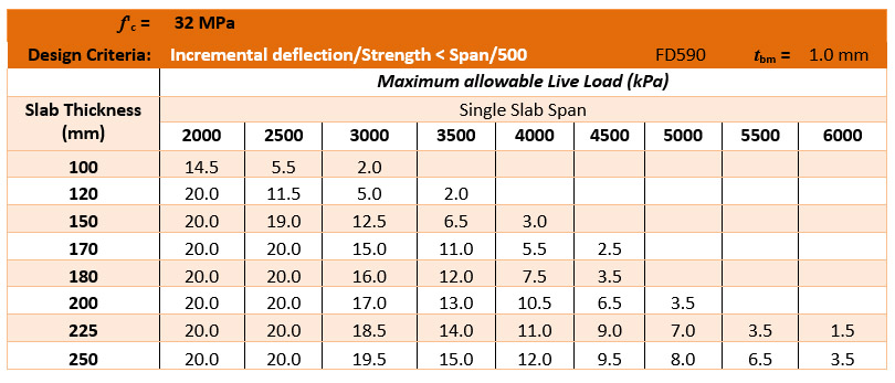
FD590 Composite Table Design Loads
The design loads for both strength and serviceability are based on the load combinations as defined in AS1170.0-2002. The design tables have been developed utilising ‘Limit State’ principles as detailed in AS/NZS 3600-2018 – Concrete Structures Standards, AS 2327-2017 – Composite Structures Standard and AS1170 – Structural Design Actions.
The design spans and slab thicknesses are defined and the allowable imposed actions (Q) for each combination is presented. The Slab thickness and the type of Span (i.e. single or continuous) are detailed for each table. The self-weight and superimposed dead loads (1kPa) are defined in accordance with AS1170 and AS2327.
The table presents the span from centre to centre, and the allowable imposed loads in the positive bending region of the span for the various base metal thicknesses. The negative reinforcement is assumed to be detailed by the design engineer with no allowance for moment redistribution.
The following assumptions are made in the presented tables:
- The type of construction is steel frame construction or equivalent
- There is a minimum support width of 100 mm at the permanent supports
- Multiple spans have equal spans, with the span measures from centre to centre of supports
- Concrete strength f’c = 32 MPa
- Concrete density is 2450 kg/m3
- Classification is A1 exposure, with 20mm cover to reinforcement
- Slab deflection limits for L/250 for total loads and L/500 for incremental deflections are imposed
- Superimposed Dead load is 0.5 kPa
- Minimum degree of crack control for shrinkage as per AS3600 is utilised
- Internal spans may be increased by 15%
- For multiple spans negative reinforcement to be as detailed by design engineer
- The appropriateness of the utilisation of the tables has been carried out by a registered structural engineer with consideration for long-term deflections and capacities considered.
- Back propping to engineering specification
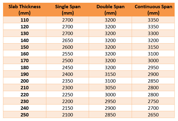
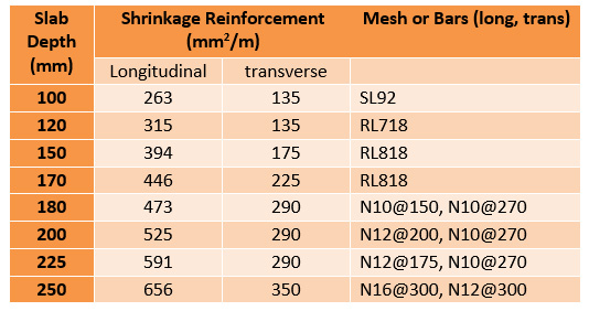
Minimum shrinkage reinforcement for FD590 slabs
(minimal crack control longitudinally)
FD590 Composite Tables – tbm = 0.75 mm – Single Span
FD590 Composite Tables – tbm = 0.75 mm – Continuous Span
FD590 Composite Tables – tbm = 0.9 mm – Single Span
FD590 Composite Tables – tbm = 0.9 mm – Continuous Span


FD590 Composite Tables – tbm = 1.0 mm – Single Span

FD590 Composite Tables – tbm = 1.0 mm – Continuous Span

